115V920Ah DC Power System
The composition of the high-frequency rectifier DC operating power system
* AC power distribution unit
* high-frequency rectifier module
* battery System
* battery inspection device
* insulation monitoring device
* charging monitoring unit
* power distribution monitoring unit
* centralized monitoring module
* other parts
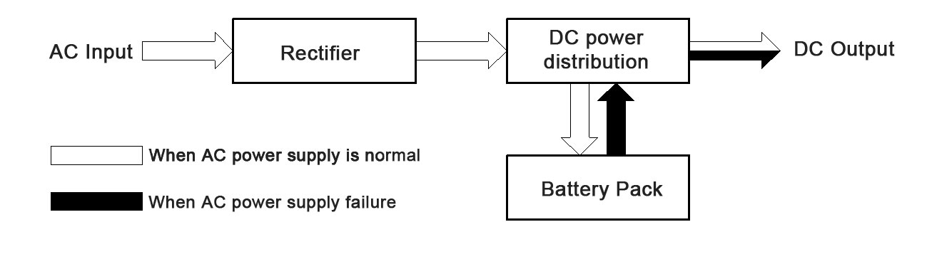
The work principle of the DC system
AC normal working condition:
When the AC input of the system supplies power normally, the AC power distribution unit supplies power to each rectifier module. The high-frequency rectification module converts AC power into DC power, and outputs it through a protective device (fuse or circuit breaker). On the one hand, it charges the battery pack, and on the other hand, it provides normal working power to the DC load through the DC power distribution feed unit.
AC power loss working state:
When the system's AC input fails and the power is cut off, the rectifier module stops working, and the battery supplies power to the DC load without interruption. The monitoring module monitors the discharge voltage and current of the battery in real time, and when the battery discharges to the set end voltage, the monitoring module gives an alarm. At the same time, the monitoring module displays and processes the data uploaded by the power distribution monitoring circuit at all times.
Design Principles for DC Systems
Battery System Overview
The battery system is composed of a LiFePO4 (lithium iron phosphate) battery cabinet, which offers high safety, long cycle life, and a high energy density in terms of weight and volume.
The battery system consists of 144pcs LiFePO4 battery cells:
each cell 3.2V 230Ah. Total energy is 105.98kwh.
36pcs cells in series, 2pcs cells in parallels=115V460AH
115V 460Ah * 2sets in parallels = 115V 920Ah
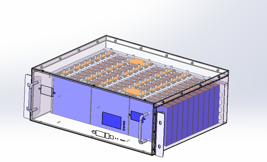
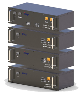
For easy transportation and maintenance:
a single set of 115V460Ah batteries is divided into 4 small containers and connected in series.
Boxes 1 to 4 are configured with a series connection of 9 cells, with 2 cells also connected in parallel.
Box 5, on the other hand, with Master Control Box inside This arrangement results in a total of 72 cells.
Two sets of these battery packs are connected in parallel,with each set independently connected to the DC power system,allowing them to function autonomously.
Battery cell

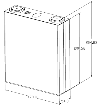
Battery cell data sheet
| No. | Item | Parameters |
| 1 | Nominal voltage | 3.2V |
| 2 | Nominal capacity | 230Ah |
| 3 | Rated working current | 115A(0.5C) |
| 4 | Max. charging voltage | 3.65V |
| 5 | Min. discharge voltage | 2.5V |
| 6 | Mass energy density | ≥179wh/kg |
| 7 | Volume energy density | ≥384wh/L |
| 8 | AC internal resistance | <0.3mΩ |
| 9 | Self-discharge | ≤3% |
| 10 | Weight | 4.15kg |
| 11 | Dimensions | 54.3*173.8*204.83mm |
Battery Pack
Battery pack data sheet
| No. | Item | Parameters |
| 1 | Battery type | Lithium iron phosphate(LiFePO4) |
| 2 | Nominal voltage | 115V |
| 3 | Rated capacity | 460Ah @0.3C3A,25℃ |
| 4 | Operating current | 50Amps |
| 5 | Peak current | 200Amps(2s) |
| 6 | Operating voltage | DC100~126V |
| 7 | Charge current | 75Amps |
| 8 | Assembly | 36S2P |
| 9 | Boxmaterial | Steel plate |
| 10 | Dimensions | Refer to our drawing |
| 11 | Weight | About 500kg |
| 12 | Operating temperature | - 20 ℃to 60 ℃ |
| 13 | Chargetemperature | 0 ℃to 45 ℃ |
| 14 | Storage temperature | - 10 ℃to 45 ℃ |
Battery box
Battery box data sheet
| Item | Parameters |
| No.1~4 box | |
| Nominal voltage | 28.8V |
| Rated capacity | 460Ah @0.3C3A,25℃ |
| Boxmaterial | Steel plate |
| Dimensions | 600*550*260mm |
| Weight | 85kg(battery only) |
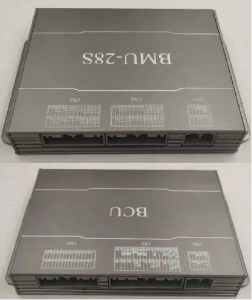
BMS Overview
The whole BMS system include:
* 1unit master BMS (BCU)
* 4units slave BMS units (BMU)
Internal communication
* CAN bus between BCU & BMUs
* CAN or RS485 between BCU & external devices
115V DC Power Rectifier
Input characteristics
| Input method | Rated three-phase four-wire |
| Input voltage range | 323Vac to 437Vac, maximum working voltage 475Vac |
| Frequency range | 50Hz/60Hz±5% |
| Harmonic current | Each harmonic does not exceed 30% |
| Inrush current | 15Atyp peak, 323Vac; 20Atyp peak, 475Vac |
| Efficiency | 93%min @380Vac full load |
| Power factor | > 0.93 @ full load |
| Start time | 3~10s |
Output characteristics
| Output voltage range | +99Vdc~+143Vdc |
| Regulation | ±0.5% |
| Ripple & Noise (Max.) | 0.5% effective value; 1% peak-to-peak value |
| Slew Rate | 0.2A/uS |
| Voltage Tolerance Limit | ±5% |
| Rated current | 40A |
| Peak current | 44A |
| Steady flow accuracy | ±1% (based on steady current value, 8~40A) |
Power Rectifier Protect function:
- Input over voltage protection
- Input under voltage protection
- Output Short circuit protection
- Output over voltage protection
- Phase lost protection
- Over temperature protection
- DC output Under voltage protection
- Others Protection
Insulating properties
Insulation resistance
| Input To Output | DC1000V 10MΩmin (at room temperature) |
| Input To FG | DC1000V 10MΩmin(at room temperature) |
| Output To FG | DC1000V 10MΩmin(at room temperature) |
Insulation withstand voltage
| Input To Output | 2828Vdc No breakdown and flashover |
| Input To FG | 2828Vdc No breakdown and flashover |
| Output To FG | 2828Vdc No breakdown and flashover |
Monitoring System
Introduction
IPCAT-X07 monitoring system is a medium-sized monitor designed to satisfy users’ conventional integration of DC screen system,This is mainly applicable to single charge system of 38AH-1000AH, collecting all kinds of data by extending the signal collecting units, linking up to remote control center through RS485 interface to implement the scheme of unattended rooms.

Compositon
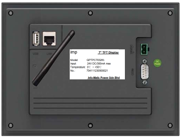
Display(touch screen):
* intelligent IoT with ARM CPU as the core
* frequency of 800MHz
* 7-inch TFT LCD display
* resolution of 800*480
* four-wire resistive touch screen
* pre-installed with McgsPro configuration software
Display Interface Details
Equipment selection for DC system
Charging device
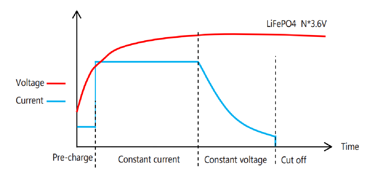
Lithium-ion battery charging method
Pack Level Protection
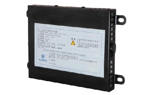
The hot aerosol fire extinguishing device is a new type of fire extinguishing device suitable for relatively enclosed spaces such as engine compartments and battery boxes.
When a fire occurs, if an open flame appears, the heat-sensitive wire detects the fire immediately and activates the fire extinguishing device inside the enclosure, simultaneously outputting a feedback signal.
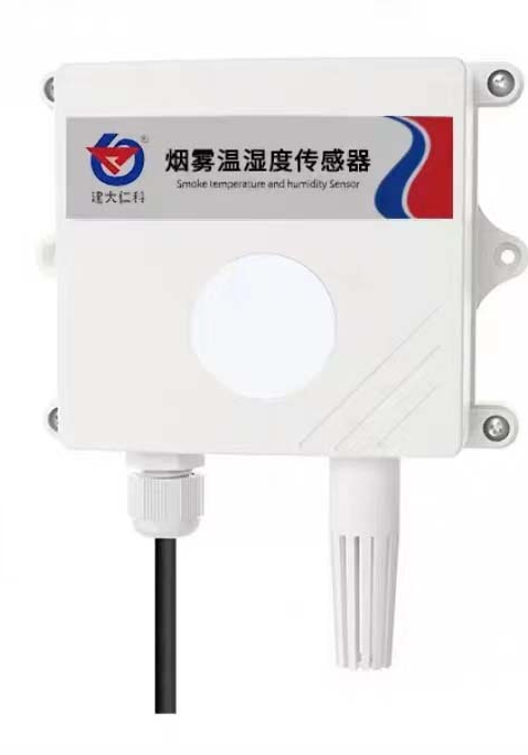
Smoke Sensor
The SMKWS three-in-one transducer simultaneously collects smoke, ambient temperature, and humidity data.
The smoke sensor collects data in the range of 0 to 10000 ppm.
The smoke sensor is installed on the top of each battery cabinet.
In the event of a thermal failure inside the cabinet causing a large amount of smoke to be generated and dispersed to the top of the cabinet, the sensor will immediately transmit the smoke data to the human-machine power monitoring unit.
Smoke alarms are classified into 3 levels. Level 1 is an alert.
After a Level 3 smoke alarm occurs in any battery cabinet, the system will shut down the charging module.
After troubleshooting, the power system must be restarted.
The default factory setting for the smoke alarm limit value is 1000 ppm.
Level 2 alarm is set at 1.2 times the limit value, and Level 3 alarm is set at 1.5 times the limit value.
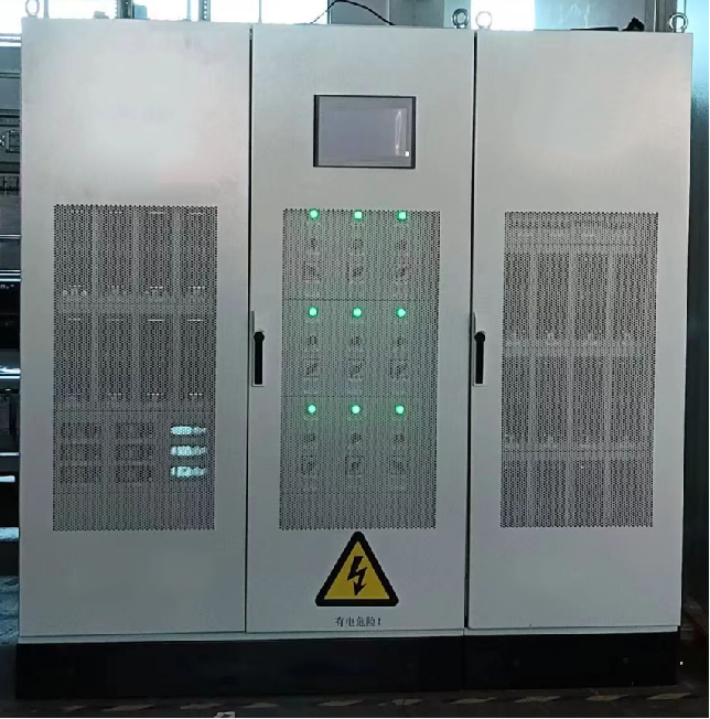
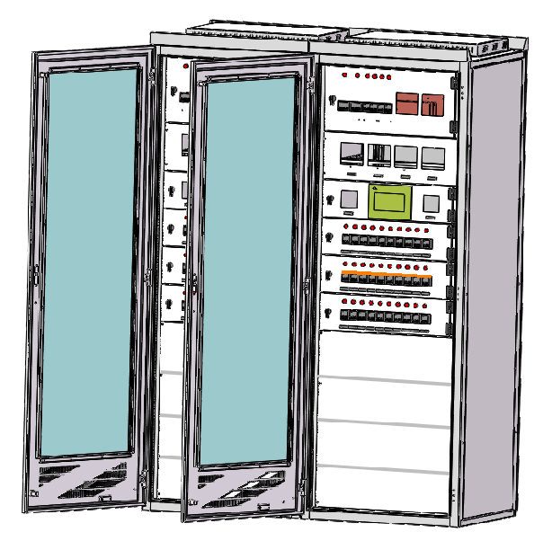
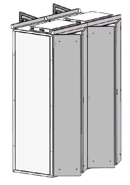
DC panel cabinet
The dimensions of one battery system cabinet are 2260(H)*800(W)*800(D)mm with color of RAL7035. In order to facilitate maintenance, management, and heat dissipation, the front door is a single-opening glass mesh door, while the back door is a double-opening full mesh door. The axis facing the cabinet doors is on the right, and the door lock is on the left. Due to the heavy weight of the battery, it is placed in the lower section of the cabinet, while other components such as high-frequency switch rectifier modules and monitoring modules are placed in the upper section. An LCD display screen is mounted on the cabinet door, providing real-time display of system operational data
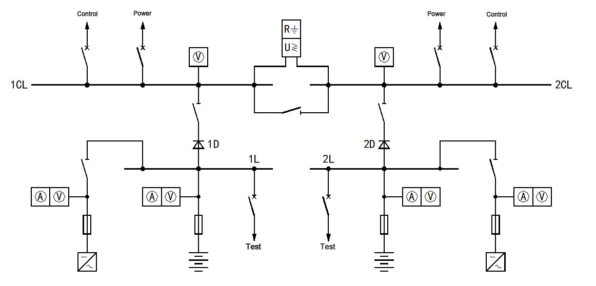
DC operation power supply electric system diagram
The DC system consists of 2 sets of batteries and 2 sets of rectifiers,and the DC bus bar is connected by two sections of single bus.
During normal operation, the bus tie switch is disconnected,and the charging devices of each bus section charge the battery through the charging bus,and provide constant load current at the same time.
The floating charge or equalizing charging voltage of the battery is the normal output voltage of the DC bus bar.
In this system scheme, when the charging device of any bus section fails or the battery pack needs to be checked for charging and discharging tests,the bus tie switch can be closed, and the charging device and battery pack of another bus section can supply power to the entire system,and the bus tie circuit It has a diode anti-return measure to prevent two sets of batteries from being connected in parallel