115V920Ah DC Power System

What is the DC Power System?
Direct current (DC) power systems are the backbone of mission-critical infrastructure, providing reliable and efficient electricity for telecommunications networks, data centers, and industrial operations. Leveraging rectifiers, batteries, inverters, and voltage regulators, these specialized power distribution solutions ensure a stable and resilient supply of DC power where AC is impractical or less suitable.
Engineered for maximum uptime and performance, DC power systems are the preferred choice in applications demanding unwavering electrical integrity. By circumventing the complexities of alternating current, these advanced solutions deliver the consistent, manageable power that supports the uninterrupted functioning of our most vital technological systems.
The work principle of the DC system
AC-to-DC Power Conversion
In normal operating mode, the AC power distribution unit channels grid electricity to the high-frequency rectification modules. These modules efficiently convert the alternating current into direct current, simultaneously charging the battery system and supplying stable DC power to the connected load through the DC distribution network. This seamless AC-to-DC conversion ensures uninterrupted operation, making the system well-suited for mission-critical applications requiring a reliable and consistent power supply.
AC power loss working state:
In the event of an AC grid outage, the system seamlessly transitions to battery backup mode. As the rectifier modules cease operation, the battery pack immediately takes over powering the connected DC loads without interruption. A monitoring module tracks the battery's discharge voltage and current in real-time, triggering alarms when the set end-of-discharge threshold is reached. Simultaneously, the module processes and displays data from the power distribution monitoring circuits, providing comprehensive status updates during the grid failure.

Design Principles for DC Systems
Battery System Overview
The battery system is composed of a LiFePO4 (lithium iron phosphate) battery cabinet, which offers high safety, long cycle life, and a high energy density in terms of weight and volume.
The Battery System consists of 144pcs LiFePO4 Battery Cells:
![]() Each cell 3.2V 230Ah. Total energy is 105.98kwh.
Each cell 3.2V 230Ah. Total energy is 105.98kwh.
![]() 36pcs cells in series, 2pcs cells in parallels=115V460AH
36pcs cells in series, 2pcs cells in parallels=115V460AH
![]() 115V 460Ah * 2sets in parallels = 115V 920Ah
115V 460Ah * 2sets in parallels = 115V 920Ah
For Easy Transportation & Maintenance:
![]() A single set of 115V460Ah batteries is divided into 4 small containers and connected in series.
A single set of 115V460Ah batteries is divided into 4 small containers and connected in series.
![]() Boxes 1 to 4 are configured with a series connection of 9 cells, with 2 cells also connected in parallel.
Boxes 1 to 4 are configured with a series connection of 9 cells, with 2 cells also connected in parallel.
![]() Box 5, on the other hand, with Master Control Box inside This arrangement results in a total of 72 cells.
Box 5, on the other hand, with Master Control Box inside This arrangement results in a total of 72 cells.
![]() Two sets of these battery packs are connected in parallel,with each set independently connected to the DC power system,allowing them to function autonomously.
Two sets of these battery packs are connected in parallel,with each set independently connected to the DC power system,allowing them to function autonomously.
Battery Cell
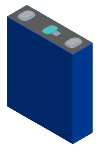
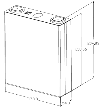
Battery cell data sheet
| No. | Item | Parameters |
| 1 | Nominal voltage | 3.2V |
| 2 | Nominal capacity | 230Ah |
| 3 | Rated working current | 115A(0.5C) |
| 4 | Max. charging voltage | 3.65V |
| 5 | Min. discharge voltage | 2.5V |
| 6 | Mass energy density | ≥179wh/kg |
| 7 | Volume energy density | ≥384wh/L |
| 8 | AC internal resistance | <0.3mΩ |
| 9 | Self-discharge | ≤3% |
| 10 | Weight | 4.15kg |
| 11 | Dimensions | 54.3*173.8*204.83mm |
Battery Pack
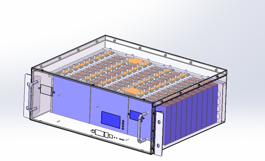
Battery pack data sheet
| No. | Item | Parameters |
| 1 | Battery type | Lithium iron phosphate(LiFePO4) |
| 2 | Nominal voltage | 115V |
| 3 | Rated capacity | 460Ah @0.3C3A,25℃ |
| 4 | Operating current | 50Amps |
| 5 | Peak current | 200Amps(2s) |
| 6 | Operating voltage | DC100~126V |
| 7 | Charge current | 75Amps |
| 8 | Assembly | 36S2P |
| 9 | Boxmaterial | Steel plate |
| 10 | Dimensions | Refer to our drawing |
| 11 | Weight | About 500kg |
| 12 | Operating temperature | - 20 ℃to 60 ℃ |
| 13 | Chargetemperature | 0 ℃to 45 ℃ |
| 14 | Storage temperature | - 10 ℃to 45 ℃ |
Battery Box
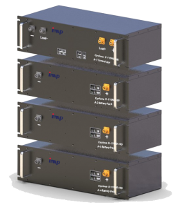
Battery box data sheet
| Item | Parameters |
| No.1~4 box | |
| Nominal voltage | 28.8V |
| Rated capacity | 460Ah @0.3C3A,25℃ |
| Boxmaterial | Steel plate |
| Dimensions | 600*550*260mm |
| Weight | 85kg(battery only) |
115V DC Power Rectifier
Input characteristics
| Input method | Rated three-phase four-wire |
| Input voltage range | 323Vac to 437Vac, maximum working voltage 475Vac |
| Frequency range | 50Hz/60Hz±5% |
| Harmonic current | Each harmonic does not exceed 30% |
| Inrush current | 15Atyp peak, 323Vac; 20Atyp peak, 475Vac |
| Efficiency | 93%min @380Vac full load |
| Power factor | > 0.93 @ full load |
| Start time | 3~10s |
Output characteristics
| Output voltage range | +99Vdc~+143Vdc |
| Regulation | ±0.5% |
| Ripple & Noise (Max.) | 0.5% effective value; 1% peak-to-peak value |
| Slew Rate | 0.2A/uS |
| Voltage Tolerance Limit | ±5% |
| Rated current | 40A |
| Peak current | 44A |
| Steady flow accuracy | ±1% (based on steady current value, 8~40A) |
Insulating Properties
Insulation Resistance
| Input To Output | DC1000V 10MΩmin (at room temperature) |
| Input To FG | DC1000V 10MΩmin(at room temperature) |
| Output To FG | DC1000V 10MΩmin(at room temperature) |
Insulation withstand Voltage
| Input To Output | 2828Vdc No breakdown and flashover |
| Input To FG | 2828Vdc No breakdown and flashover |
| Output To FG | 2828Vdc No breakdown and flashover |
Monitoring System
Introduction
The IPCAT-X07 is a medium-scale monitoring solution tailored to meet the integration needs of conventional DC power systems. Designed to support single-charge systems ranging from 38Ah to 1000Ah, this versatile unit collects comprehensive data by interfacing with extended signal acquisition modules.
Through its RS485 connectivity, the IPCAT-X07 enables remote monitoring and control from a central command center, facilitating the unattended operation of mission-critical power infrastructure.

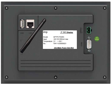
Display Interface Details
Equipment selection for DC system
Charging device
Lithium-ion Battery charging Method
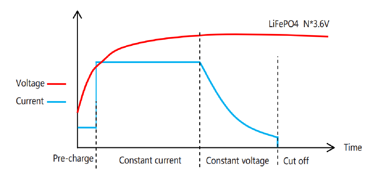
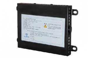
Pack Level Protection
The hot aerosol fire extinguishing device is a new type of fire extinguishing device suitable for relatively enclosed spaces such as engine compartments and battery boxes.
When a fire occurs, if an open flame appears, the heat-sensitive wire detects the fire immediately and activates the fire extinguishing device inside the enclosure, simultaneously outputting a feedback signal.
Smoke Sensor
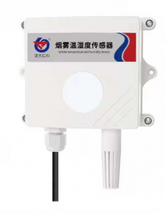
![]() The SMKWS three-in-one transducer simultaneously collects smoke, ambient temperature, and humidity data.
The SMKWS three-in-one transducer simultaneously collects smoke, ambient temperature, and humidity data.
![]() The smoke sensor collects data in the range of 0 to 10000 ppm.
The smoke sensor collects data in the range of 0 to 10000 ppm.
![]() The smoke sensor is installed on the top of each battery cabinet.
The smoke sensor is installed on the top of each battery cabinet.
In the event of a thermal failure inside the cabinet causing a large amount of smoke to be generated and dispersed to the top of the cabinet, the sensor will immediately transmit the smoke data to the human-machine power monitoring unit.
DC Panel Cabinet
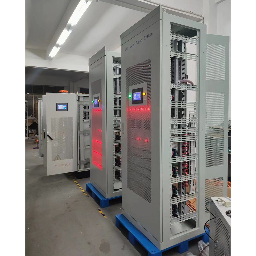
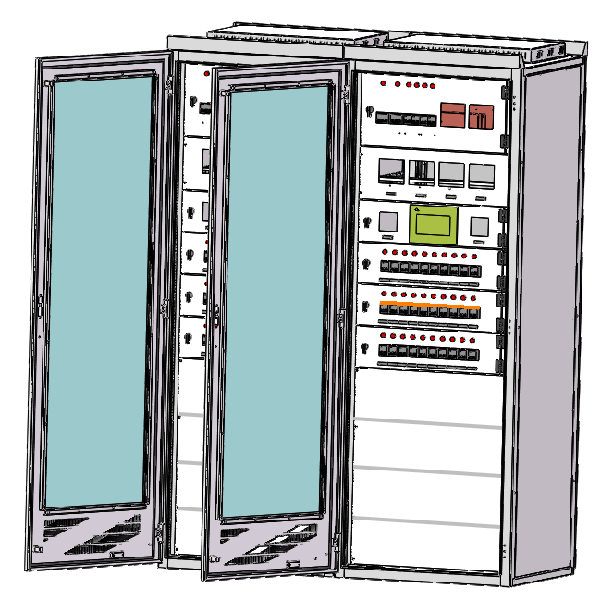
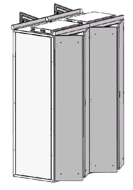
Engineered for hassle-free maintenance and thermal management, the battery system cabinet measures 2260(H) x 800(W) x 800(D)mm in a RAL7035 color scheme. The single-opening glass mesh front door and double-opening full mesh rear door facilitate easy access and airflow. With the door hinges positioned on the right and the locks on the left, the cabinet's ergonomic layout enhances user convenience.
To accommodate the heavy battery modules, the lower section houses the power source, while the upper compartment houses the high-frequency rectifier and monitoring units. An integrated LCD display provides real-time status updates, enabling comprehensive system oversight.
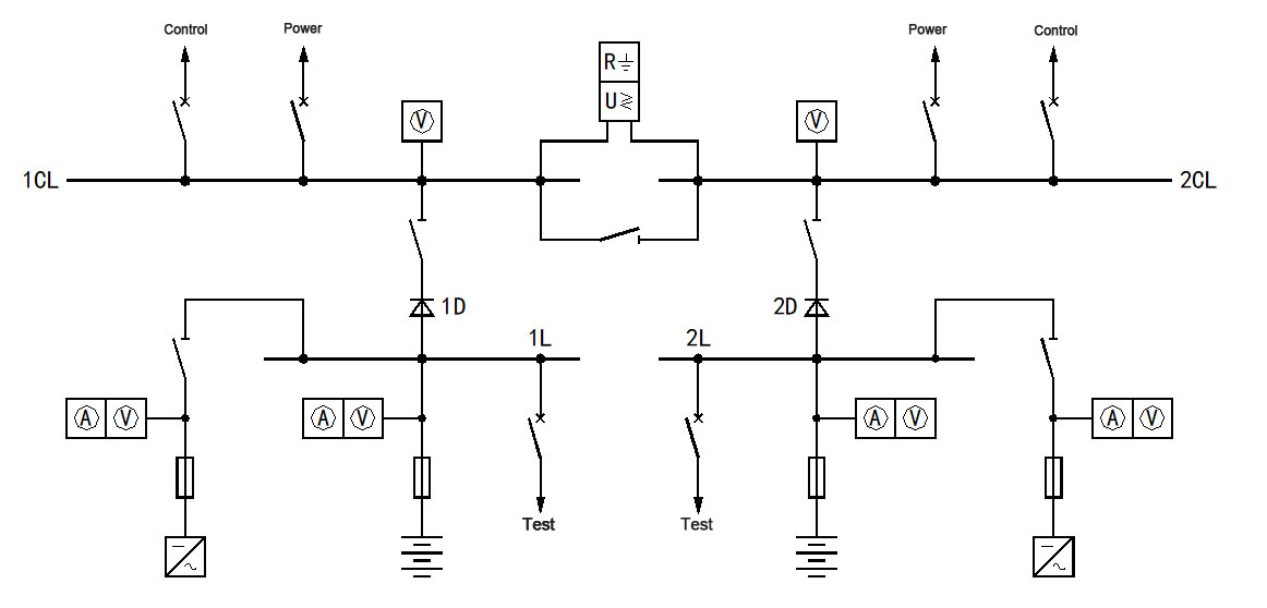
DC Operation Power Supply Electric System Diagram
1. DC System Configuration:
![]() 2 sets of batteries
2 sets of batteries
![]() 2 sets of rectifiers
2 sets of rectifiers
![]() DC bus bar connected by two single-bus sections
DC bus bar connected by two single-bus sections
2. Normal Operation:
![]() Bus tie switch is disconnected
Bus tie switch is disconnected
![]() Each bus section's charging devices:
Each bus section's charging devices:
![]() Charge the battery through the charging bus
Charge the battery through the charging bus
![]() Provide constant load current
Provide constant load current
![]() Battery's floating/equalization charge voltage matches the DC bus output voltage
Battery's floating/equalization charge voltage matches the DC bus output voltage
3. Redundancy and Maintenance:
![]() When a charging device fails or battery testing is required:
When a charging device fails or battery testing is required:
![]() Bus tie switch can be closed
Bus tie switch can be closed
![]() Healthy bus section's charging device and battery can power the entire system
Healthy bus section's charging device and battery can power the entire system
![]() Diode anti-return measure prevents parallel connection of battery packs
Diode anti-return measure prevents parallel connection of battery packs
This design ensures uninterrupted power delivery and facilitates maintenance without service disruptions.
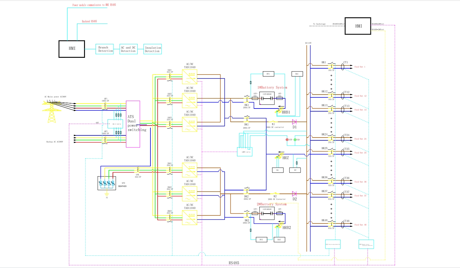
Electrical Schematics
Application
DC power supply systems are widely used in various industries and fields. Some common applications of DC power systems include:
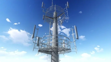
1. Telecommunications: DC power systems are widely used in telecommunications infrastructure, such as cell phone towers, data centers and communication networks, to provide reliable, uninterrupted power to critical equipment.
2. Renewable energy: DC power systems are used in renewable energy systems, such as solar photovoltaic power generation and wind power generation installations, to convert and manage DC power generated by renewable energy sources.
3. Transportation: Electric vehicles, trains, and other forms of transportation usually use DC power systems as their propulsion and auxiliary systems.
4. Industrial Automation: Many industrial processes and automation systems rely on DC power to control systems, motor drives and other equipment.
5. Aerospace and Defense: DC power systems are used in aircraft, spacecraft and military applications to meet a variety of power needs, including avionics, communications systems and weapons systems.
6. Energy Storage: DC power systems are an integral part of energy storage solutions such as battery storage systems and uninterruptible power supplies (UPS) for commercial and residential applications.
These are just a few examples of the diverse applications of DC power systems, demonstrating their importance in multiple industries.


